This manual provides essential information for safe and effective hot tub use‚ covering installation‚ operation‚ and maintenance․ It ensures a relaxing and therapeutic experience for all users to enjoy․
1․1 Importance of Reading the Manual
Reading the manual ensures safe and proper usage‚ highlighting essential safety precautions‚ maintenance routines‚ and troubleshooting tips․ It provides detailed guidance on operation‚ chemical balance‚ and care‚ maximizing your hot tub experience while preventing potential issues․ Understanding the manual is crucial for longevity and enjoyment of your hot tub․
1․2 Overview of Hot Tub Components
Your hot tub consists of key components: the control panel for operation‚ jets for massage‚ lighting for ambiance‚ a filter for water quality‚ a heater for temperature adjustment‚ pumps for water circulation‚ and the shell that houses everything․ Understanding these parts ensures proper functionality and maintenance‚ enhancing your overall hot tub experience․

Safety Instructions
Ensure a safe and enjoyable experience by following these guidelines․ Always check water temperature‚ supervise children‚ and follow health precautions for users with medical conditions․
2․1 General Safety Precautions
Adhere to essential safety guidelines to ensure a secure hot tub experience․ Always maintain water temperature below 104°F‚ supervise children‚ and avoid using electrical devices nearby․ Do not use the hot tub if you have open wounds or certain medical conditions without consulting a healthcare professional․
2․2 Important Safety Warnings
Always follow critical safety warnings to prevent accidents․ Ensure the hot tub is properly grounded and avoid overloading it with excessive users․ Never enter the tub under the influence of alcohol or drugs․ Be cautious of slipping on wet surfaces and keep loose clothing away from jets and other moving parts․
2․3 Safety Instructions for Canada
Canadian users must adhere to specific safety standards․ Ensure compliance with local electrical codes and CSA (Canadian Standards Association) requirements․ Regularly test water chemistry and maintain proper sanitation levels․ Always supervise children and avoid prolonged exposure to extreme temperatures․ Familiarize yourself with emergency shut-off procedures to ensure a safe hot tub experience for all users․

Initial Installation and Setup
Ensure proper placement on a sturdy‚ level surface․ Connect electrical components safely‚ following local codes․ Level the hot tub to ensure even weight distribution and optimal performance․ Test all systems before first use to confirm everything functions correctly․
3․1 Choosing the Right Location
Position your hot tub on a firm‚ level surface‚ ensuring it’s away from overhead obstructions․ A clean‚ dry path minimizes debris and moisture tracked inside․ Consider privacy and accessibility when selecting the location․ Ensure proximity to a power source and drainage system for easy maintenance․ Proper placement enhances safety‚ convenience‚ and overall enjoyment of your hot tub experience․
3․2 Leveling the Hot Tub Surface
Ensure the hot tub is placed on a level surface to maintain structural integrity and proper functionality․ Use a spirit level to check evenness‚ adjusting the base pads as needed․ A properly leveled surface prevents uneven water distribution‚ ensures safe operation‚ and prolongs the lifespan of the hot tub components․ Double-check all four corners for accuracy․

Operating the Hot Tub
Understand your control panel‚ adjust temperature settings‚ and activate jets and lighting․ Regular operation ensures a safe and enjoyable experience‚ enhancing relaxation and therapy benefits effectively․
4․1 Understanding the Control Panel
The control panel is the central hub for operating your hot tub; It features buttons and knobs to adjust temperature‚ jets‚ and lighting․ Familiarize yourself with its functions to customize your experience․ Refer to the owner’s manual for detailed instructions on each control’s purpose and operation․ Proper use ensures safety‚ efficiency‚ and an enjoyable soaking experience every time․
4․2 Adjusting Temperature Settings
Adjust the temperature using the control panel․ The system heats water at 1-2 degrees per hour․ Use the up and down arrows to set your desired temperature․ Ensure it’s between 98°F and 104°F for safety․ Always test the water before entering․ Proper temperature control enhances relaxation and prevents discomfort․ Refer to the manual for specific instructions on your model’s temperature adjustment features․
4․3 Using Jets and Lighting
Activate jets via the control panel to enjoy therapeutic massage settings․ Adjust jet intensity for comfort․ Lighting enhances ambiance‚ with options to change colors and brightness․ Use these features to create a relaxing experience․ Ensure jets and lights are turned off when not in use to conserve energy and maintain optimal performance․ Always follow manual guidelines for safe operation․
Maintenance and Care
Regular cleaning‚ proper water hygiene‚ and consistent upkeep are crucial for maintaining your hot tub’s functionality and longevity․ Follow scheduled maintenance routines to ensure optimal performance․
5․1 Cleaning the Hot Tub Shell
Regular cleaning of the hot tub shell is essential for maintaining hygiene and appearance․ Use a mild‚ non-abrasive cleaner and a soft cloth to wipe down surfaces weekly․ Avoid harsh chemicals or abrasive materials that may damage the shell․ For tougher stains‚ apply a gentle scrubbing product specifically designed for hot tubs․ Rinse thoroughly and dry to prevent water spots․ Deep clean every few months for optimal results․ This routine will help prevent bacteria buildup and keep your hot tub looking like new․ Always avoid using bleach or acidic cleaners‚ as they can harm the shell material․ For vinyl shells‚ consider using a vinyl conditioner to maintain its shine and durability․ Regular cleaning not only enhances aesthetics but also ensures a safe and enjoyable soaking experience․ It’s a simple yet crucial step in maintaining your hot tub’s longevity and performance․
5․2 Proper Filter Maintenance
Regular filter maintenance is crucial for clean‚ clear water and system efficiency․ Clean the cartridge weekly with a mild cleaner‚ rinse thoroughly‚ and allow it to dry․ Soak the filter monthly in a specific cleaning solution to remove stubborn debris․ Replace the filter every 1-2 years or as recommended by the manufacturer․ Always follow the manufacturer’s instructions for cleaning and replacing to ensure optimal performance and hygiene․ Proper filter care prevents bacteria buildup and prolongs the life of your hot tub’s equipment․
5․3 Sanitizing the Water
Sanitizing the water is essential for maintaining hygiene and safety․ Use chlorine or bromine tablets‚ following the manufacturer’s guidelines for proper dosage․ Regularly test and adjust sanitizer levels to ensure they remain within the recommended range․ Improper levels can lead to health risks or equipment damage․ Always allow the sanitizer to circulate fully before use for maximum effectiveness and safety․

Troubleshooting Common Issues
This section helps identify and resolve common problems like low water flow or faulty heaters․ Follow step-by-step solutions to fix issues quickly and safely‚ ensuring optimal performance․
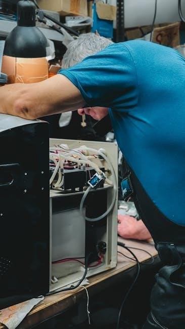
6․1 Identifying Common Problems
Identify common issues such as low water flow‚ malfunctioning jets‚ or temperature fluctuations․ Check for blockages in filters or pipes and ensure all components are functioning properly․ Regular maintenance can prevent many problems‚ ensuring your hot tub runs smoothly․ Consult the manual for specific troubleshooting steps to address these issues effectively and safely․
6․2 Step-by-Step Troubleshooting Guide
Start by identifying the issue‚ then refer to the manual for specific solutions․ Turn off the power and check for obvious problems like tripped breakers or loose connections․ Clean or replace filters‚ inspect jets‚ and ensure proper water levels․ For complex issues‚ contact a professional․ This guide helps resolve common problems efficiently‚ ensuring optimal performance and safety․

Chemicals and Water Treatment
Proper chemical use ensures clean‚ safe water․ Regularly test pH levels‚ sanitize‚ and balance chemicals to maintain hygiene and protect equipment․ Follow guidelines for optimal results․
7․1 Essential Hot Tub Chemicals
Key chemicals include chlorine or bromine for sanitization‚ pH balancers to maintain water stability‚ and shock treatments for oxidizing contaminants․ Algaecides prevent algae growth‚ while clarifiers enhance water clarity․ Regular testing ensures optimal levels‚ keeping the water safe and enjoyable for all users while preserving equipment longevity․ Proper chemical balance is crucial for a healthy spa experience․
7․2 Guide to Water Testing and Balancing
Regularly test pH‚ alkalinity‚ and calcium hardness levels using test strips or kits․ Adjust chemicals as needed to maintain optimal ranges (pH: 7․2-7․8‚ alkalinity: 80-120 ppm‚ calcium hardness: 175-275 ppm)․ Proper balancing prevents corrosion‚ scaling‚ and cloudiness‚ ensuring safe and enjoyable use․ Always follow the manufacturer’s instructions for testing and adjustment to maintain water quality and equipment longevity․

Regular Maintenance Routines
Regular maintenance ensures your hot tub operates efficiently and safely․ Follow weekly and monthly schedules for cleaning‚ filter checks‚ and water testing to keep it in top condition․
8․1 Weekly Maintenance Tasks
Weekly maintenance involves cleaning the hot tub shell‚ testing water chemistry‚ and sanitizing․ Regularly inspect filters and ensure they are clean or replaced as needed․ Additionally‚ check all jets and lighting for proper function․ These tasks help maintain water clarity‚ prevent bacterial growth‚ and ensure optimal performance of your hot tub system․
8;2 Monthly Maintenance Checklist
Perform a detailed cleaning of the filter and replace it if necessary․ Check and balance water chemistry‚ including pH and alkalinity levels․ Inspect the hot tub cover for damage and clean it thoroughly․ Drain and refill the tub every 3-4 months to maintain hygiene and prevent chemical buildup․ This ensures long-term efficiency and safety of your hot tub․
Winterization and Drainage
Prepare your hot tub for winter by draining and cleaning it thoroughly․ Proper drainage ensures the system remains free of water‚ preventing damage from freezing temperatures․
9․1 Preparing Your Hot Tub for Winter
- Drain the hot tub completely and clean the shell and filters thoroughly․
- Disconnect and drain all plumbing lines to prevent freezing damage․
- Apply a winterizing kit or antifreeze to protect the system․
- Ensure the cover is tightly secured to keep out debris and moisture․
- Store any accessories and chemicals in a dry‚ cool place․
9․2 Proper Drainage Techniques
Attach the drainage hose to the valve and direct it to a suitable drain site․ Open the valve slowly to allow water to flow out completely․ For inflatable models‚ unscrew the deflation valve and attach the inflation hose to the pump for efficient emptying․ Always follow manufacturer guidelines to prevent damage․
Resources and Support
Access online manuals‚ troubleshooting guides‚ and customer support for assistance with your hot tub․ Visit the manufacturer’s website or contact their support team for help․
10․1 Accessing Online Manuals
Accessing online manuals is straightforward․ Visit the manufacturer’s website and select your hot tub model to download the manual․ Many brands offer digital versions for easy access‚ ensuring you can reference installation‚ operation‚ and maintenance instructions anytime․ Additionally‚ some companies provide troubleshooting guides and FAQs to address common issues․ Always check the official website for the most accurate and updated information to ensure optimal performance and safety․
10․2 Contacting Customer Support
Contacting customer support is easy and recommended for any questions or concerns․ Reach out via phone‚ email‚ or live chat on the manufacturer’s website․ Many companies also provide dedicated support pages with FAQs and troubleshooting guides․ Ensure to have your model number ready for faster assistance‚ helping you resolve issues promptly and enjoy uninterrupted use of your hot tub․

Advanced Features and Upgrades
Discover advanced features like LED lighting‚ jet upgrades‚ and smart controls to enhance your hot tub experience․ Explore additional accessories‚ such as furniture and entertainment systems‚ for ultimate relaxation․
11․1 Upgrading Your Hot Tub Experience
Enhance your hot tub experience with advanced upgrades like LED lighting‚ jets‚ and smart controls․ These upgrades offer improved functionality‚ comfort‚ and style․ Consider adding accessories such as Wi-Fi connectivity‚ waterfalls‚ or Bluetooth speakers to create a luxurious and relaxing environment․ Regular maintenance and proper installation ensure optimal performance of these upgrades․ Customize your hot tub to meet your preferences for a truly personalized experience․ Accessories like cup holders and headrests can further elevate your relaxation․ Always consult the manual for compatibility and installation guidelines to ensure safety and longevity of your hot tub system․ Upgrading allows you to enjoy the latest innovations in spa technology‚ making every soak more enjoyable and rejuvenating․ Explore the available options to transform your hot tub into a premium retreat․ Proper care and maintenance of upgrades will extend their lifespan and keep your hot tub functioning at its best․ By investing in quality upgrades‚ you can enhance the overall experience and enjoy your hot tub for years to come․
11․2 Exploring Additional Accessories
Discover a wide range of accessories to enhance your hot tub experience‚ such as spa steps‚ covers‚ and cleaning tools․ These items improve safety‚ convenience‚ and maintenance․ Accessories like aromatherapy kits and spa pillows add comfort and relaxation․ Ensure compatibility with your hot tub model for optimal performance․ Regularly check and maintain accessories to keep your hot tub in top condition․ Always follow the manufacturer’s guidelines for installation and care․ Accessories can personalize your spa experience‚ making it more enjoyable and tailored to your needs․ Explore available options to find the perfect additions for your hot tub setup․ Properly maintained accessories will extend the life of your spa and ensure continued satisfaction․ By selecting the right accessories‚ you can create a harmonious and inviting environment for relaxation and rejuvenation․ Accessories are designed to complement your hot tub‚ offering both functional and aesthetic benefits․ Choose wisely to maximize your spa experience and enjoy lasting comfort․ Always prioritize quality and durability when selecting accessories for your hot tub․ This ensures reliability and longevity‚ providing you with years of enjoyment and relaxation․ Accessories play a crucial role in maintaining your hot tub’s performance and enhancing your overall satisfaction․ Invest in the right ones to elevate your spa experience to new heights․ Remember to refer to your manual for specific accessory recommendations and guidelines․ Accessories are a great way to customize your hot tub to suit your lifestyle and preferences․ They offer practical solutions and luxurious touches that can transform your spa time․ Whether you’re looking for convenience‚ comfort‚ or style‚ there’s an accessory to meet your needs․ Always consider safety and compatibility when choosing accessories to ensure a seamless and enjoyable experience․ By exploring additional accessories‚ you can truly make your hot tub your own personal sanctuary․ Accessories not only enhance functionality but also add to the visual appeal of your spa area․ They are an excellent way to upgrade your hot tub without major renovations․ Accessories can help you maintain your hot tub more efficiently‚ saving you time and effort in the long run․ Explore the variety of accessories available to find the perfect fit for your needs and preferences․ Accessories are a smart investment for any hot tub owner looking to enhance their spa experience․ They offer practical benefits and luxurious touches that make every soak more enjoyable․ Always choose high-quality accessories that align with your hot tub’s specifications for optimal performance․ By adding the right accessories‚ you can create a spa environment that is both functional and inviting․ Accessories are designed to make your hot tub experience more comfortable‚ convenient‚ and enjoyable․ They are a great way to personalize your spa and make it a true retreat․ Explore the options available and find the accessories that best suit your lifestyle and needs․ Accessories can make a significant difference in the overall enjoyment of your hot tub․ They offer solutions to common challenges and add luxurious touches that elevate your spa experience․ Always follow the manufacturer’s guidelines when selecting and installing accessories to ensure safety and compatibility․ By choosing the right accessories‚ you can enhance the performance and aesthetics of your hot tub‚ creating a truly exceptional experience․ Accessories are a key part of maintaining and enjoying your hot tub․ They provide practical solutions and luxurious enhancements that make your spa time more relaxing and enjoyable․ Explore the various options available to find the perfect accessories for your hot tub․ Accessories can help you get the most out of your hot tub experience․ They offer functionality‚ comfort‚ and style‚ making every soak more satisfying․ Always opt for high-quality accessories that are compatible with your hot tub model for optimal results․ By investing in the right accessories‚ you can create a spa environment that meets your every need and preference․ Accessories are a great way to customize and enhance your hot tub experience․ They provide practical benefits and luxurious touches that make your spa time truly special․ Explore the available options to find the accessories that best complement your hot tub setup․ Accessories play a vital role in ensuring your hot tub remains a place of relaxation and rejuvenation․ They offer solutions to maintenance challenges and add comfort and style to your spa experience․ Always choose accessories that are designed for your specific hot tub model to ensure proper fit and function․ By selecting the right accessories‚ you can enjoy your hot tub for years to come‚ knowing it’s well-maintained and tailored to your needs․ Accessories are an essential part of your hot tub experience‚ offering both practical and luxurious benefits․ They help maintain your spa’s performance and enhance your relaxation time․ Explore the various accessories available to find the perfect additions for your hot tub․ Accessories are designed to make your hot tub experience more enjoyable and convenient․ They provide solutions to common maintenance tasks and add comfort and style to your spa․ Always refer to your manual for specific accessory recommendations to ensure compatibility and safety․ By choosing the right accessories‚ you can create a spa environment that is both functional and inviting․ Accessories are a great investment for any hot tub owner‚ offering both practical benefits and luxurious touches․ They enhance the overall experience‚ making every soak more enjoyable․ Explore the options available and find the accessories that best suit your needs and preferences․ Accessories can make a significant difference in the comfort and convenience of your hot tub experience․ They offer practical solutions and luxurious enhancements that elevate your spa time․ Always follow the manufacturer’s guidelines when selecting and installing accessories to ensure safety and compatibility․ By adding the right accessories‚ you can create a spa environment that is both relaxing and rejuvenating․ Accessories are a key part of enjoying your hot tub to the fullest․ They provide practical benefits and luxurious touches that make every soak more satisfying․ Explore the various options available to find the perfect accessories for your hot tub․ Accessories are designed to enhance your hot tub experience‚ offering both functionality and style․ They help maintain your spa’s performance and add to your relaxation and enjoyment․ Always choose high-quality accessories that are compatible with your hot tub model for optimal results․ By selecting the right accessories‚ you can create a spa environment that meets your every need and preference․ Accessories are a great way to personalize and enhance your hot tub experience․ They provide practical solutions and luxurious touches that make your spa time truly special․ Explore the available options to find the accessories that best complement your hot tub setup․ Accessories play a crucial role in ensuring your hot tub remains a place of relaxation and rejuvenation․ They offer solutions to maintenance challenges and add comfort and style to your spa experience․ Always select accessories that are designed for your specific hot tub model to ensure proper fit and function․ By choosing the right accessories‚ you can enjoy your hot tub for years to come‚ knowing it’s well-maintained and tailored to your needs․ Accessories are an essential part of your hot tub experience‚ offering both practical and luxurious benefits․ They help maintain your spa’s performance and enhance your relaxation time․ Explore the various accessories available to find the perfect additions for your hot tub․ Accessories are designed to make your hot tub experience more enjoyable and convenient․ They provide solutions to common maintenance tasks and add comfort and style to your spa․ Always refer to your manual for specific accessory recommendations to ensure compatibility and safety․ By choosing the right accessories‚ you can create a spa environment that is both functional and inviting․ Accessories are a great investment for any hot tub owner‚ offering both practical benefits and luxurious touches․ They enhance the overall experience‚ making every soak more enjoyable․ Explore the options available and find the accessories that best suit your needs and preferences․ Accessories can make a significant difference in the comfort and convenience of your hot tub experience․ They offer practical solutions and luxurious enhancements that elevate your spa time․ Always follow the manufacturer’s guidelines when selecting and installing accessories to ensure safety and compatibility․ By adding the right accessories‚ you can create a spa environment that is both relaxing and rejuvenating․ Accessories are a key part of enjoying your hot tub to the fullest․ They provide practical benefits and luxurious touches that make every soak more satisfying․ Explore the various options available to find the perfect accessories for your hot tub․ Accessories are designed to enhance your hot tub experience‚ offering both functionality and style․ They help maintain your spa’s performance and add to your relaxation and enjoyment․ Always choose high-quality accessories that are compatible with your hot tub model for optimal results․ By selecting the right accessories‚ you can create a spa environment that meets your every need and preference․ Accessories are a great way to personalize and enhance your hot tub experience․ They provide practical solutions and luxurious touches that make your spa time truly special․ Explore the available options to find the accessories that best complement your hot tub setup․ Accessories play a crucial role in ensuring your hot tub remains a place of relaxation and rejuvenation․ They offer solutions to maintenance challenges and add comfort and style to your spa experience․ Always select accessories that are designed for your specific hot tub model to ensure proper fit and function․ By choosing the right accessories‚ you can enjoy your hot tub for years to come‚ knowing it’s well-maintained and tailored to your needs․ Accessories are an essential part of your hot tub experience‚ offering both practical and luxurious benefits․ They help maintain your spa’s performance and enhance your relaxation time․ Explore the various accessories available to find the perfect additions for your hot tub․ Accessories are designed to make your hot tub experience more enjoyable and convenient․ They provide solutions to common maintenance tasks and add comfort and style to your spa․ Always refer to your manual for specific accessory recommendations to ensure compatibility and safety․ By choosing the right accessories‚ you can create a spa environment that is both functional and inviting․ Accessories are a great investment for any hot tub owner‚ offering both practical benefits and luxurious touches․ They enhance the overall experience‚ making every soak more enjoyable․ Explore the options available and find the accessories that best suit your needs and preferences․ Accessories can make a significant difference in the comfort and convenience of your hot tub experience․ They offer practical solutions and luxurious enhancements that elevate your spa time․ Always follow the manufacturer’s guidelines when selecting and installing accessories to ensure safety and compatibility․ By adding the right accessories‚ you can create a spa environment that is both relaxing and rejuvenating; Accessories are a key part of enjoying your hot tub to the fullest․ They provide practical benefits and luxurious touches that make every soak more satisfying․ Explore the various options available to find the perfect accessories for